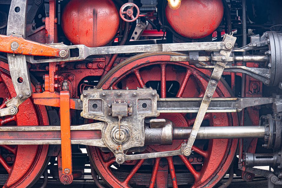
The Complete Engineering Guide to EMD Locomotive Spare Parts

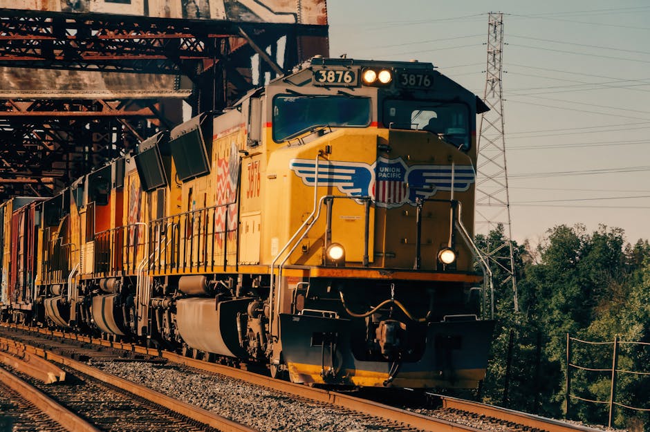
The Complete Engineering Guide to EMD® Locomotive Spare Parts
A professional reference for railway engineers, fleet maintenance teams, overhaul workshops, and procurement specialists covering EMD 567, 645, and 710 series engines — component specifications, manufacturing processes, failure analysis, inspection standards, and global sourcing best practices.
1 Understanding EMD Locomotives
Chapter Overview. Electro-Motive Diesel (EMD) has been the dominant force in diesel-electric locomotive engineering for over eight decades. This chapter examines the company’s evolution, its three primary engine families, and the industries that depend on EMD-powered locomotives worldwide.
History & Evolution
Electro-Motive Diesel began as the Electro-Motive Corporation in 1922, building gasoline-powered rail cars before introducing its first diesel-electric streamliner in 1934. By 1938 EMD had launched the 567 engine, a two-stroke diesel design that would define North American railroading for three decades. The 567’s modular architecture—individual cylinder power assemblies, unit injectors, and a robust under-slung crankshaft—set a new standard for maintainability and reliability.
In 1965 EMD introduced the 645 series, increasing cylinder displacement from 567 to 645 cubic inches. The 645 became the most widely produced locomotive engine in history, powering iconic models such as the SD40-2, GP38-2, and SD45. Over 20,000 645-powered locomotives remain in service today.
EMD’s two-stroke design philosophy was driven by the physics of diesel-electric traction. Higher torque density per pound of engine weight meant locomotives could produce more tractive effort within a given axle load limit. The uniflow scavenging system, where intake ports in the cylinder liner are uncovered by the descending piston while exhaust valves in the head open, provides efficient cylinder clearing with fewer moving parts than four-stroke equivalents. This design influences every aspect of component engineering: piston ring packs must seal against ports, cylinder liners must accommodate port windows, and turbocharger matching must account for the unique pressure wave dynamics of the two-stroke cycle.
The 710 series, launched in 1984, brought further improvements in power density, emissions, and durability. With 710 cubic inches per cylinder and advanced metallurgy, the 710G engine now powers the SD70ACe, SD70MAC, and export models including the Class 66. It remains in production as EMD’s flagship prime mover.
Power Flow in an EMD Locomotive
This mechanical-to-electrical-to-mechanical energy conversion path is the defining characteristic of diesel-electric traction. The engine never mechanically drives the wheels—it drives a generator that powers electric traction motors. This arrangement eliminates the need for a mechanical transmission and allows the engine to operate at its optimal speed range regardless of locomotive ground speed.
Engine Families
EMD 567 Series (1938–1965)
The 567 engine family includes the 567, 567A, 567B, 567BC, 567C, 567CR, and 567D variants. Displacement of 567 cubic inches per cylinder. Configuration: 6, 8, 12, and 16 cylinders. Power range: 600–2,400 hp. The 567 pioneered the unit-injector design that EMD continues to use today. Despite being out of production for over 50 years, thousands of 567-powered locomotives still operate worldwide, supported by a robust aftermarket parts industry.
EMD 645 Series (1965–1988)
The 645 series increased displacement to 645 cubic inches per cylinder. Variants include 645E, 645E3, 645E4, 645F, 645F3B, and 645G. Configuration: 6, 8, 12, 16, and 20 cylinders. Power range: 1,000–3,600 hp. The 645E3 variant in the SD40-2 is widely regarded as one of the most reliable locomotive engines ever built. Parts availability remains excellent due to the large installed base.
EMD 710 Series (1984–Present)
The 710G series features 710 cubic inches per cylinder with improved combustion efficiency, higher power density, and reduced emissions. Configuration: 8, 12, 16, and 20 cylinders. Power range: 2,800–6,000 hp. The 710 series incorporates finite-element-optimized components, improved cooling, and advanced electronic fuel injection on later variants. It remains EMD’s current production engine.
Engine Series Comparison
| Parameter | 567 Series | 645 Series | 710 Series |
|---|---|---|---|
| Displacement / Cylinder | 567 cu in (9.3 L) | 645 cu in (10.6 L) | 710 cu in (11.6 L) |
| Production Years | 1938–1965 | 1965–1988 | 1984–Present |
| Power Range | 600–2,400 hp | 1,000–3,600 hp | 2,800–6,000 hp |
| Cylinder Configurations | 6, 8, 12, 16 | 6, 8, 12, 16, 20 | 8, 12, 16, 20 |
| Rated RPM | 800–935 | 835–904 | 904–950 |
| Typical Overhaul Interval | 15,000–20,000 hrs | 18,000–25,000 hrs | 20,000–30,000 hrs |
| Parts Availability | Aftermarket only | OEM + Aftermarket | Current production |
| Active Locomotives | ~5,000+ | ~20,000+ | ~12,000+ |
Understanding the differences between the 567, 645, and 710 families is essential before selecting replacement parts. The wrong crankshaft or bearing set can render an engine inoperable. With this foundation in place, the next chapter examines the critical components that determine overhaul intervals, fuel economy, and reliability.
2 Critical EMD Spare Parts
Chapter Overview. Every EMD locomotive contains over 4,000 individual components. This chapter examines the 12 most critical wear items—the parts that determine overhaul intervals, fuel economy, reliability, and operating cost. Each component is presented using a consistent format covering function, materials, manufacturing, failure modes, inspection, and procurement guidance.
| Component | Function | Typical Life | Critical Failure Mode |
|---|---|---|---|
| Crankshaft | Converts reciprocating to rotary motion | 15,000–25,000 hrs | Fatigue cracking at fillet radii |
| Connecting Rod | Transmits piston force to crankshaft | 10,000–20,000 hrs | Bolt fatigue or bearing seizure |
| Main & Rod Bearings | Support rotating assemblies with oil film | 8,000–15,000 hrs | Overlay wear, fatigue, or wipe |
| Piston & Ring Assembly | Seal combustion pressure, transfer load | 10,000–20,000 hrs | Crown cracking, ring land wear |
| Cylinder Head | Seal combustion chamber, house valves | 15,000–25,000 hrs | Thermal cracking between valves |
| Cylinder Liner | Provide precision bore surface for piston | 15,000–25,000 hrs | Cavitation erosion, bore wear |
| Fuel Injector | Atomize fuel for combustion | 5,000–10,000 hrs | Nozzle erosion, carbon deposits |
| Turbocharger | Compress intake air using exhaust energy | 8,000–15,000 hrs | Bearing failure, blade damage |
| Water Pump | Circulate engine coolant | 6,000–12,000 hrs | Seal failure, impeller erosion |
| Oil Pump | Maintain lubrication system pressure | 10,000–20,000 hrs | Gear wear, pressure loss |
| Valves & Guides | Control gas flow into and out of cylinder | 8,000–15,000 hrs | Valve guttering, guide wear |
| Camshaft | Actuate valves and injectors | 15,000–25,000 hrs | Lobe wear, follower pitting |
Crankshaft
Function
The crankshaft converts the reciprocating motion of the pistons into rotational torque to drive the generator, accessories, and traction motors. It is the single most expensive and critical component in the engine. An EMD 16-710 crankshaft weighs approximately 1,200 kg and must withstand peak firing pressures exceeding 2,000 psi across all cylinders simultaneously.
Materials & Manufacturing
EMD crankshafts are forged from vacuum-degassed alloy steel. SAE 4340 (nickel-chromium-molybdenum) is preferred over 4140 for larger engines because its deeper hardenability allows through-hardening of thicker web sections while maintaining acceptable toughness. The 1.8% nickel content shifts the time-temperature-transformation curve, enabling martensite formation at lower quench rates and reducing the risk of quench cracking. The forging process aligns grain flow along the crank cheek and fillet contours, placing the strongest grain orientation in the direction of peak stress. Fillet rolling after heat treatment compresses the fillet surface, creating a residual compressive stress layer of 400–800 MPa that opposes the tensile service stresses where fatigue cracks typically initiate. Induction hardening of journal surfaces to 50–55 HRC provides a wear-resistant bearing surface while the core retains toughness at 285–341 HB. Finish grinding achieves journal surface finish of 0.2–0.4 μm Ra with runout held to within 0.025 mm.
Common Failure Modes
Fatigue cracking originating at the fillet radii between the journal and web is the most common failure mechanism. Causes include: excessive torsional vibration, improper bearing clearance leading to impact loading, and metallurgical defects in the original forging. Cracks typically initiate below the surface and propagate slowly, making ultrasonic inspection essential during overhaul.
Inspection During Overhaul
- Dimensional check of all main and crankpin journals (diameter, taper, out-of-round)
- Magnetic particle inspection of all fillet radii and oil hole edges
- Ultrasonic inspection of web sections and oil passages
- Runout measurement at center main journals
- Surface finish verification of all ground journals
Procurement Guidance
When sourcing replacement crankshafts, request material test certificates (mill certificates), heat treatment records, dimensional inspection reports, and NDT documentation. Premium aftermarket crankshafts manufactured from forged alloy steel with modern CNC grinding and induction hardening can match original OEM quality.
Crankshaft Installation Notes
Crankshaft installation requires precise attention to main bearing clearance, thrust bearing end-play, and torsional vibration damper condition. Bearing clearance should be verified using Plastigage or micrometer measurement at each main journal. Thrust bearing clearance for EMD engines is typically 0.008–0.015 in (0.20–0.38 mm). The torsional vibration damper must be inspected for rubber deterioration or viscous fluid leakage; a failed damper subjects the crankshaft to destructive torsional stresses that can cause fatigue failure within hours.
Connecting Rod
Function
The connecting rod transmits the full combustion force from the piston to the crankshaft. It operates under cyclic tension-compression loading and must resist buckling, fatigue, and high-temperature exposure. A failed connecting rod at speed can destroy the engine block and surrounding components. EMD connecting rods feature an I-beam cross-section for optimal stiffness-to-weight ratio, with the big end split at an angle to permit assembly around the crankpin.
Materials & Manufacturing
Connecting rods are forged from alloy steel, then rough machined, heat treated to 285–341 HB, shot peened for fatigue enhancement, and finish machined. The big-end bore is precision-ground to 0.4–0.8 μm Ra. The small end accepts a floating piston pin bushing. Connecting rod bolts are critical safety items and must be replaced at every overhaul. Typical tensile strength for finished rods is 180–210 ksi with elongation of 12–16%. Shot peening induces compressive residual stress at the surface, significantly improving fatigue life under cyclic loading.
Common Failure Modes
- Bolt fatigue failure (most catastrophic — always replace bolts)
- Bearing seizure in big end (oil starvation or clearance loss)
- Fatigue cracking at the rod neck or I-beam section
- Piston pin bushing wear (small end)
Inspection Checklist
- Magnetic particle inspection of entire rod
- Big end bore diameter and roundness
- Small end bushing ID
- Center-to-center length
- Bolt hole thread condition (gauged)
- Surface finish of big end bore
Torque Specifications
| Application | Bolt Grade | Torque (ft-lb) | Stretch (in) |
|---|---|---|---|
| 567 Connecting Rod | SAE Grade 8 | 180–200 | 0.012–0.015 |
| 645 Connecting Rod | SAE Grade 8 / Premium | 220–250 | 0.014–0.017 |
| 710 Connecting Rod | Premium Alloy Steel | 300–340 | 0.017–0.020 |
| Main Bearing Cap (710) | Premium Alloy Steel | 450–500 | 0.020–0.025 |
| Cylinder Head (710) | Premium Alloy Steel | 180–220 | 0.010–0.013 |
Main & Connecting Rod Bearings
Function
Main bearings support the crankshaft within the engine block. Connecting rod bearings (big-end bearings) allow the rod to pivot on the crankpin. Both create a hydrodynamic oil film that separates the moving surfaces under load. Bearing clearance is critical: too tight causes seizure, too loose causes vibration and oil pressure loss.
Bearing Selection by Engine Series
| Application | Standard Journal Dia. | Wall Thickness | Undersizes Available |
|---|---|---|---|
| 567 Main Bearing | 165.100–165.175 mm | 3.175 mm | 0.254, 0.508 mm |
| 645 Main Bearing | 177.800–177.875 mm | 3.175 mm | 0.254, 0.508 mm |
| 710 Main Bearing | 190.500–190.575 mm | 3.175 mm | 0.254, 0.508 mm |
| 567 Rod Bearing | 139.700–139.725 mm | 2.540 mm | 0.254, 0.508 mm |
| 645 Rod Bearing | 152.400–152.425 mm | 2.540 mm | 0.254, 0.508 mm |
| 710 Rod Bearing | 165.100–165.125 mm | 2.540 mm | 0.254, 0.508 mm |
Common Failure Modes
- Overlay fatigue (micro-cracking of bearing surface)
- Wipe (metal transfer due to oil film breakdown)
- Corrosion from contaminated oil (acid or water ingress)
- Cavitation erosion (high-frequency pressure collapse)
- Insufficient crush (bearing movement in housing)
Pistons & Piston Rings
Function
The piston assembly seals the combustion chamber, transmits pressure forces to the connecting rod, and manages heat rejection to the cylinder wall. The ring pack controls compression sealing, oil control, and heat transfer. EMD power assemblies typically include the piston, rings, pin, and retainers as a matched unit.
Materials & Construction
Modern EMD pistons feature a forged aluminum alloy body with a cast-in ductile iron ring carrier for the top ring groove. The piston pin is case-hardened alloy steel (58–62 HRC). Ring packs consist of a barrel-faced compression ring, a taper-faced intermediate ring, and a two-piece oil control ring. Chrome or molybdenum coatings extend ring life. The piston skirt is cam-turned to provide controlled clearance that accommodates thermal expansion while maintaining oil film control.
Piston cooling is critical in EMD two-stroke engines. Oil jets directed at the underside of the piston crown remove combustion heat and maintain piston temperature within safe limits. Blocked or misaligned cooling jets are a common cause of piston crown cracking. During overhaul, always verify that all piston cooling jets are clear, properly aimed, and delivering adequate flow.
Forged vs Cast Piston Comparison
| Property | Forged Piston | Cast Piston |
|---|---|---|
| Grain Structure | Aligned, dense (directional strength) | Random, may have micro-porosity |
| Fatigue Strength | Higher (20–30% improvement) | Adequate for moderate loads |
| Thermal Conductivity | Higher (denser grain boundaries) | Slightly reduced |
| High-Temp Strength | Superior up to 400°C | Lower; risk of crown deformation |
| Weight Variation | Tighter control | Greater variation |
| Cost | Higher | Lower |
| EMD Application | High-output 710 engines | Lower-rated 567 / early 645 |
Common Failure Modes
- Crown cracking from thermal stress or detonation
- Ring land wear (loss of ring groove dimensional control)
- Ring sticking (carbon deposits in grooves)
- Skirt wear (insufficient lubrication or bore distortion)
- Piston pin bore elongation
Inspection Points
- Crown visual inspection for cracks (dye penetrant)
- Ring groove width and side clearance
- Piston pin bore diameter
- Skirt diameter at measurement band
- Ring gap in cylinder liner (confirm with liner installed)
Cylinder Heads
Function
The cylinder head seals the top of the combustion chamber, houses the intake and exhaust valves, fuel injector, and provides passages for cooling water and scavenging air. It is subjected to extreme thermal gradients and cyclic pressure loading.
Construction
EMD cylinder heads are precision cast from alloy iron or steel. They feature separate intake and exhaust valve ports, a central injector bore, and water jacket passages. The flame face (combustion side) is machined flat and must remain within tight flatness tolerances to prevent gas or coolant leakage.
Common Failure Modes
- Thermal cracking between valve seats (most common)
- Valve seat recession or distortion
- Injector tube cracking or leakage
- Water jacket corrosion or erosion
- Thread damage in injector or valve guide bores
Inspection Requirements
- Hydrostatic pressure test (water jacket integrity)
- Magnetic particle inspection of flame face and valve bridge
- Valve seat concentricity and width
- Guide bore diameter and alignment
- Injector bore condition
- Flame face flatness
Reconditioning Procedure
Cylinder heads that pass NDT inspection can be reconditioned for continued service. The process begins with complete disassembly and cleaning. Valve seat inserts are replaced if worn or recessed, with new seats pressed in and cut to the correct angle (typically 45° intake, 30° exhaust for EMD engines). Valve guides are replaced with new bronze or cast iron guides, pressed in and reamed to correct stem clearance (0.002–0.004 in for intake, 0.003–0.005 in for exhaust). The injector tube is replaced if cracked or leaking, and the injector bore is inspected for thread condition. The flame face is resurfaced only enough to restore flatness; excessive removal reduces the compression ratio and weakens the valve bridge section. After reconditioning, the head is pressure-tested again to verify integrity.
Cylinder Liners
Function
The cylinder liner provides the precision bore surface against which the piston rings seal combustion pressure while allowing the piston to slide freely. It also transfers heat from the piston rings to the cooling water jacket. EMD engines use wet liners, meaning the outer surface is in direct contact with coolant.
Critical Tolerances
| Parameter | Typical Specification | Wear Limit |
|---|---|---|
| Bore diameter (710 series) | 250.000–250.050 mm | 250.150 mm max |
| Bore taper (max) | 0.025 mm over liner length | 0.080 mm |
| Bore out-of-round (max) | 0.015 mm | 0.050 mm |
| Surface finish (bore) | 0.4–0.8 μm Ra plateau | 1.2 μm Ra max |
| Liner flange height above block | 0.050–0.150 mm | Tolerance must be maintained |
| Hardness (parent material) | 220–280 HB | Min 200 HB |
Construction
Liners are centrifugally cast from alloy iron to produce a dense, uniform microstructure. The bore is honed to 0.4–0.8 μm Ra with a plateau finish that retains oil for ring lubrication. The outer diameter features anti-cavitation coatings or treatments to resist pitting from coolant bubble collapse. The liner flange seals against the cylinder head gasket.
Wet Liner vs Dry Liner Comparison
| Property | Wet Liner (EMD) | Dry Liner |
|---|---|---|
| Coolant Contact | Direct — outer surface contacts coolant | Indirect — pressed into block bore |
| Heat Transfer | Superior (direct conduction to coolant) | Reduced (gap to block, then to coolant) |
| Replacement Difficulty | Moderate — O-ring seal replacement required | More difficult — requires pressing out |
| Cavitation Risk | Present — requires inhibitor in coolant | Minimal — block protects outer surface |
| Cost per Liner | Higher (precision OD, O-ring grooves) | Lower (simpler geometry) |
| Bore Distortion | Less (uniform cooling around circumference) | More (non-uniform block temperature) |
Common Failure Modes
- Cavitation erosion on the coolant side (most common)
- Scuffing or scoring on the bore surface
- Bore taper or out-of-round wear
- Cracking at the flange radius
- O-ring groove damage
Fuel Injectors
Function
The unit injector combines fuel metering, pressurization, and atomization in a single assembly. At each injection event, the injector raises fuel pressure to 15,000–25,000 psi and delivers a precisely timed, atomized spray into the combustion chamber. Injection timing and spray quality directly affect power output, fuel consumption, and emissions.
Fuel System Flow Diagram
EMD unit injectors are cam-actuated. A rocker arm driven by the camshaft pushes the injector plunger downward, pressurizing fuel in the barrel. Injection begins when pressure exceeds the nozzle opening pressure (typically 3,000–5,000 psi) and ends when the plunger uncovers a spill port, instantly dropping pressure and closing the nozzle. This mechanical injection system requires no high-pressure fuel lines between pump and injector, eliminating a common failure point found in four-stroke engines.
Failure & Testing
Injectors should be tested at every overhaul. Key tests include pop pressure verification, spray pattern observation, leak-down rate, and flow comparison across all injectors. Mismatched injector delivery rates cause cylinder-to-cylinder imbalance and rough running.
- Confirm part number matches engine model and series
- Verify pop pressure within specification
- Check spray pattern for even atomization
- Measure flow rate and match within 2% of set average
- Inspect nozzle tip for erosion or carbon buildup
- Replace copper gasket and O-rings at every installation
- Torque injector clamp to specification
Turbocharger
Function
The turbocharger uses exhaust gas energy to compress intake air, increasing the mass of air available for combustion. EMD turbochargers are typically single-stage, axial-flow turbines driving a centrifugal compressor. Boost pressure ranges from 15 to 40 psi depending on engine model and power setting. The turbocharger rotor assembly in a 710 engine can exceed 30,000 rpm at full load, requiring precision dynamic balancing to within 0.5 g-mm or better.
Operating Conditions
Exhaust gas temperatures at the turbine inlet can reach 650–750°C (1,200–1,380°F) under full load. The turbine housing and wheel are therefore manufactured from high-temperature nickel-based alloys (Inconel or equivalent) to resist creep, oxidation, and thermal fatigue. The compressor wheel is typically aluminum alloy or titanium in high-performance variants. Bearing systems use floating-ring or semi-floating designs with pressure-fed lubrication from the engine oil system.
Common Failure Modes
- Bearing failure (oil starvation or contamination)
- Foreign object damage to turbine or compressor blades
- Shaft fatigue fracture
- Carbon buildup on turbine end seal
- Compressor wheel rubbing on housing
Inspection Points
- Shaft end-play and radial clearance
- Compressor and turbine wheel visual inspection
- Bearing housing condition
- Oil drain passage cleanliness
- Wastegate operation (if fitted)
Water Pump
Function
The water pump circulates coolant through the engine block, cylinder heads, oil cooler, and radiator to maintain proper engine operating temperature. EMD engines typically use centrifugal pumps driven from the accessory gear train. Flow rates range from 200 to 600 gpm depending on engine size.
Failure & Replacement
Seal failure is the most common water pump issue, typically indicated by coolant leakage from the weephole. Impeller erosion (from cavitation or coolant chemistry) reduces flow capacity. Bearing wear causes shaft misalignment and seal damage. Always replace the pump as a complete unit or with a factory-remanufactured assembly.
Inspection Points
- Weephole inspection for coolant leakage (early seal failure indicator)
- Impeller visual inspection for erosion, pitting, or damage
- Bearing axial and radial play measurement
- Shaft surface condition at seal contact area
- Housing wear at wear ring locations
- Pressure test for internal bypass leakage
Oil Pump
Function
The oil pump supplies pressurized lubricant to all engine bearings, piston cooling jets, turbocharger, and valve gear. EMD engines use gear-type pumps with pressure regulation. Adequate oil pressure is essential for bearing survival—most bearing failures trace back to lubrication system issues.
Operating Principles
EMD engines use a gear-type oil pump driven from the accessory gear train. The pump draws oil from the crankcase sump through a strainer, pressurizes it through a gerotor or spur-gear set, and delivers it through the oil cooler and full-flow filters before distributing to main galleries. A pressure relief valve regulates maximum system pressure, bypassing excess flow back to the sump.
Critical Checks During Overhaul
During overhaul, measure gear backlash, end clearance, and housing wear. Verify pressure relief valve operation. Inspect the pump drive coupling for wear. Low oil pressure at idle after overhaul often indicates excessive bearing clearance or a worn pump. Oil pump cavitation, indicated by noisy operation and pressure fluctuations, can result from restricted suction, excessive oil viscosity, or low oil level.
Valves & Valve Train
Function
Intake valves admit scavenging air into the cylinder; exhaust valves allow combustion gases to exit. Each cylinder has two intake and two exhaust valves actuated by the camshaft through followers, pushrods, and rocker arms. Valve timing directly affects engine power and efficiency.
Common Failure Modes
- Exhaust valve guttering (burning of valve face margin)
- Valve seat recession (face wear into seat insert)
- Stem wear and guide clearance enlargement
- Valve head cracking from thermal stress
- Carbon buildup on stem causing sticking
- Rocker arm bushing wear causing lash variation
- Spring fatigue or fracture (loss of cylinder seal)
Valve Maintenance
Valve lash adjustment is a critical maintenance task. Intake valve lash for EMD engines is typically 0.015–0.025 in, exhaust 0.025–0.035 in when cold. Incorrect lash affects timing, power output, and can accelerate component wear. Valve rotators (where fitted) should be checked for free rotation. Always replace valve stem seals during overhaul. Stellite-faced exhaust valves provide superior high-temperature wear resistance and are recommended for severe-duty applications.
Valve Guide Comparison
| Property | Bronze Valve Guide | Cast Iron Valve Guide |
|---|---|---|
| Wear Resistance | Excellent (longer service life) | Good (adequate for normal duty) |
| Heat Transfer | Superior (higher thermal conductivity) | Moderate |
| Scuff Resistance | High (dissimilar metal to valve stem) | Moderate (same metal family) |
| Cost | Higher | Lower |
| Typical Application | Exhaust valves (high-temp environment) | Intake valves (lower temperature) |
| Stem Clearance (typical) | 0.003–0.005 in exhaust | 0.002–0.004 in intake |
Camshaft
Function
The camshaft controls the timing and duration of valve opening and fuel injection. EMD engines use a single camshaft per cylinder bank with lobes ground to precisely control injector timing and valve events. Camshaft timing is critical for engine performance and emissions.
Operating Conditions
The camshaft is subjected to high contact stresses at the lobe-follower interface, particularly on the injection lobes where fuel injection pressure creates peak loading. EMD camshafts are supported by precision-insert bearings or replaceable bearing shells, each with pressure-fed lubrication from the main oil gallery. Camshaft timing is set at installation using alignment marks on the gear train and must be verified after any major overhaul.
Inspection & Replacement
During overhaul, inspect all lobe profiles for wear, pitting, or spalling. Measure journal diameters and verify camshaft straightness. Check cam follower rollers for flat spots. If lobe wear exceeds 0.050 mm, replace the camshaft and all followers as a matched set. Timing gear backlash should be measured at multiple positions around the camshaft rotation. Camshaft thrust clearance must be verified to prevent axial movement that can alter timing.
The 12 components covered in this chapter represent the vast majority of EMD engine wear-related downtime. Understanding how each part fails and how to inspect it is the first step toward extending overhaul intervals. The next chapter explains how these components are manufactured—from raw material selection through final inspection—and why manufacturing quality is inseparable from component reliability.
3 Manufacturing Process
Chapter Overview. The reliability of an EMD replacement component depends directly on how it is made. This chapter traces the manufacturing journey from raw material to finished part, highlighting the engineering decisions that determine quality, consistency, and service life.
Manufacturing Flow
Raw Material Selection
Every EMD component begins with material specification. Alloy steel grades (SAE 4140, 4340, 8620) are selected for strength, toughness, and fatigue resistance. Cast iron grades are chosen for wear resistance and thermal conductivity. Material certificates from the steel mill provide traceability from melt to finished part.
| Component | Typical Material | Key Property Required |
|---|---|---|
| Crankshaft | SAE 4340 (Ni-Cr-Mo) | High fatigue strength, through-hardening |
| Connecting Rod | SAE 4140 / 4340 | Tensile strength, impact resistance |
| Cylinder Head | Alloy cast iron / steel | Thermal fatigue resistance, pressure tightness |
| Cylinder Liner | Centrifugal cast alloy iron | Wear resistance, cavitation resistance |
| Piston (body) | Forged aluminum alloy | Light weight, thermal conductivity |
| Piston (ring carrier) | Ductile iron | Wear resistance at top ring groove |
| Camshaft | Hardened alloy steel / chilled iron | Lobe wear resistance, dimensional stability |
| Turbocharger Turbine | Inconel / Ni-based superalloy | Creep strength at 750°C |
| Fuel Injector Barrel | Tool steel (high-carbon, high-chrome) | Wear resistance at 20,000+ psi |
| Main Bearings | Steel-backed copper-lead / Al-Sn | Fatigue strength, embedability |
Material selection directly determines in-service performance. For example, SAE 4340 (nickel-chromium-molybdenum) provides superior hardenability and fatigue strength for crankshafts, while SAE 8620 (nickel-chromium-molybdenum case-hardening) is preferred for gears requiring a hard wear surface and tough core. Cast iron grades for cylinder liners must balance wear resistance against machinability and thermal conductivity to prevent hot spots.
Forging vs Casting
| Property | Forged Components | Cast Components |
|---|---|---|
| Grain Structure | Aligned with component shape | Random equiaxed |
| Fatigue Strength | Superior (20–40% higher) | Adequate for many static loads |
| Impact Resistance | Higher | Lower |
| Design Complexity | Limited by die geometry | Virtually unlimited |
| Cost per Part | Higher (tooling-intensive) | Lower for complex shapes |
| Typical Applications | Crankshafts, rods, gears | Heads, housings, covers, pistons |
Heat Treatment
Heat treatment transforms raw material properties to meet the demanding requirements of locomotive service. Through-hardening provides uniform strength throughout the section. Induction hardening selectively hardens wear surfaces (journals, lobes) while maintaining core toughness. Case hardening (carburizing or nitriding) produces a hard wear-resistant surface with a tough core.
Each heat treatment cycle must be precisely controlled. Austenitizing temperature, soak time, quench rate, and tempering temperature all affect final mechanical properties. Improper heat treatment can result in components that meet dimensional checks but fail prematurely in service due to inadequate hardness, excessive brittleness, or residual stress.
CNC Machining & Finishing
Modern CNC machining centers produce components to tolerances measured in micrometers. Finish grinding achieves surface finishes of 0.2–0.4 μm Ra on bearing journals. Cylinder bores are plateau-honed to 0.4–0.8 μm Ra. Coordinate measuring machines (CMM) verify every critical dimension against the engineering specification.
Post-machining processes such as shot peening (connecting rods, crankshaft fillets), burnishing (journal surfaces), and superfinishing (bearing surfaces) further enhance fatigue life. These surface treatments induce compressive residual stresses that resist crack initiation and propagation under cyclic loading.
Manufacturing quality is invisible to the naked eye. A component that meets its dimensional print may still fail early if heat treatment was incorrect or if subsurface defects went undetected. That is why quality assurance—the subject of the next chapter—is not an add-on but an integral part of the manufacturing process.
4 Quality Assurance
Chapter Overview. A component that meets its dimensional drawing is not necessarily a good component. Quality assurance in EMD parts manufacturing encompasses material verification, process control, non-destructive testing, and complete traceability.
Non-Destructive Testing (NDT)
| Method | Application | Detects |
|---|---|---|
| Magnetic Particle Inspection (MPI) | Ferrous components | Surface and near-surface cracks |
| Ultrasonic Testing (UT) | Crankshafts, rods, thick sections | Subsurface voids, inclusions, cracks |
| Dye Penetrant Inspection (DPI) | Non-ferrous components | Surface cracks, porosity |
| Hardness Testing | All heat-treated parts | Surface and core hardness |
| Dimensional CMM Inspection | All precision components | Dimension, form, position tolerance |
| Surface Finish Measurement | Journals, bores, seal surfaces | Ra, Rz roughness parameters |
NDT methods are selected based on component material, geometry, and the types of defects likely to occur. MPI is the primary method for crankshaft fillet radii and connecting rods because it reliably detects the tight fatigue cracks that develop at stress concentration points. Ultrasonic testing is essential for thick-section components where subsurface defects may not be visible on the surface. Dye penetrant is used on non-ferrous components such as aluminum pistons and copper-lead bearings.
The sequence of NDT inspection matters. Rough-machined components should receive initial NDT screening to identify material defects before finishing operations. After finish machining, a second NDT pass checks for grinding burns and cracks introduced during final processing. After heat treatment, hardness testing verifies that the thermal cycle achieved the required mechanical properties throughout the component cross-section.
Reputable manufacturers maintain NDT procedures certified to recognized standards (ASTM, ASME, or ISO). Inspector certification to SNT-TC-1A or ISO 9712 ensures that inspections are performed by qualified personnel. Request NDT procedure qualification records and inspector certifications as part of supplier qualification.
Material Traceability
Each component should be traceable to its original material heat through documented mill certificates. Premium manufacturers maintain batch tracking that links every finished part to its heat treatment cycle, machining operation, and inspection results.
- Material test certificates (mill certificates) with melt and chemistry
- Heat treatment process record with time-temperature data
- Dimensional inspection report (CMM or gauging)
- NDT reports (MPI, UT, DPI as applicable)
- Surface finish measurement report
- Certificate of conformance
Quality assurance is the bridge between manufacturing and reliable in-service performance. However, even well-manufactured components eventually wear or fail. The ability to diagnose problems quickly and accurately is the next critical skill for any fleet maintenance team.
5 Failure Analysis & Troubleshooting
Chapter Overview. Rapid diagnosis of engine problems reduces downtime and prevents catastrophic secondary damage. This chapter provides a structured approach to failure analysis with symptom-to-cause reference tables for the most common EMD engine issues.
Symptom-Based Troubleshooting
Engine Will Not Start
- No fuel supply (tank level, shutoff valve, filters)
- Low battery voltage (check voltage, connections)
- Starter motor or solenoid malfunction
- Air in fuel system (bleed and check suction side)
- Low compression (perform compression test)
- Governor not energized or faulty shutdown solenoid
- Engine stop switch activated or ground fault
Low Power Output
- Air filter restriction (check indicator, replace if needed)
- Turbocharger under-boosting (check boost pressure)
- Fuel injector problems (test spray pattern and flow)
- Injection timing incorrect
- Low compression (one or more cylinders)
- Governor malfunction
- Fuel quality issues (water, sediment, wrong cetane)
- Exhaust back-pressure too high (restricted muffler or after-treatment)
Excessive Exhaust Smoke
| Smoke Color | Likely Cause | Action |
|---|---|---|
| Black | Over-fueling / insufficient air | Check air filter, turbo boost, injector calibration |
| White | Unburned fuel / coolant ingress | Check injector nozzles, fuel quality, cylinder head gasket |
| Blue | Oil burning | Check piston rings, valve guides, turbo seals |
High Oil Consumption
- Worn piston rings or cylinder liner (blow-by test)
- Worn valve guides (measure stem-to-guide clearance)
- Turbocharger oil seal leakage
- External oil leaks (gaskets, seals, lines)
- Crankcase overfilled or wrong oil viscosity
- Oil cooler internal leak (oil mixing with coolant)
Low Oil Pressure
- Low oil level
- Oil pump wear or pressure relief valve stuck
- Worn bearings (excessive clearance)
- Oil diluted with fuel (perform oil analysis)
- Incorrect oil viscosity
- Oil filter restricted
Engine Overheating
- Low coolant level or coolant loss
- Water pump failure or impeller erosion
- Radiator blockage or fan drive malfunction
- Thermostat stuck closed
- Incorrect coolant mixture
- Air in cooling system
Abnormal Engine Noise
- Bearing knock (low oil pressure or worn bearings)
- Piston slap (excessive piston-to-liner clearance)
- Valve train noise (incorrect lash or worn components)
- Gear train noise (worn or damaged gears)
- Turbocharger noise (shaft play or blade contact)
Vibration & Rough Running
- Injector delivery mismatch (cylinder-to-cylinder imbalance)
- Governor hunting (incorrect gain or droop settings)
- Crankshaft torsional vibration (damper failure)
- Engine mounting deterioration
- Propeller shaft or coupling misalignment
- Individual cylinder misfire (identify by cutting out cylinders one at a time)
Fuel System Issues
| Symptom | Fuel System Check | Probable Cause |
|---|---|---|
| Hard starting, white smoke | Check fuel quality, water content, and cetane number | Contaminated or low-quality fuel |
| Power loss at high RPM | Measure fuel pressure at injector inlet | Fuel filter restriction or pump wear |
| Black smoke, high fuel consumption | Test injector pop pressure and spray pattern | Injector nozzle erosion or dribble |
| Engine hunts or surges at idle | Check fuel return line restriction | Air in fuel or governor instability |
| Cylinder knock at low RPM | Check injection timing on affected cylinder | Advance timing or incorrect injector height |
| Fuel in oil (dilution) | Perform oil analysis for fuel content | Injector leakage or leak-off line failure |
Cooling System Diagnosis
| Symptom | Likely Cause | Diagnostic Step |
|---|---|---|
| Engine running hot, coolant not circulating | Water pump failure or impeller slip | Check pump discharge pressure, inspect impeller |
| Coolant loss without visible leak | Internal leak (head gasket, liner seal, oil cooler) | Pressure test system, check oil for coolant contamination |
| Overheating at high load only | Radiator blockage, fan drive problem | Check radiator air flow, fan clutch engagement |
| Coolant foaming in expansion tank | Combustion gas leakage into cooling system | Perform combustion leak test on coolant |
| Low coolant temperature in cold weather | Thermostat stuck open | Replace thermostat, verify warm-up rate |
Top 10 Causes of EMD Engine Failure
- Lubrication system failure (oil starvation, contamination, incorrect viscosity)
- Cooling system failure (coolant loss, pump failure, blockage)
- Fuel system problems (contaminated fuel, injector failure, poor filtration)
- Bearing fatigue and overlay wear
- Crankshaft fatigue cracking
- Cylinder head thermal cracking
- Piston seizure or crown cracking
- Turbocharger failure (bearing or blade)
- Valve train wear or breakage
- Improper maintenance or installation procedures
Preventive Maintenance Schedule
| Interval | Check / Service |
|---|---|
| Daily | Engine oil level, coolant level, air filter indicator, fuel filter water drain, visual leak check |
| Weekly | Battery voltage and electrolyte level, drive belt tension, radiator fin cleaning |
| Monthly | Oil sample for analysis, coolant sample for additive levels, air filter condition, fuel filter differential pressure |
| Every 3,000 hrs | Valve lash adjustment, injector timing check, turbocharger bearing clearance, water pump seal inspection |
| Every 6,000 hrs | Fuel injector pop test, cylinder compression test, crankcase pressure measurement, cooling system pressure test |
| Every Overhaul (15K–25K hrs) | Complete strip-down, dimensional inspection, NDT of all critical components, bearing replacement, ring replacement, head reconditioning or replacement |
Lubrication & Coolant Specifications
| Parameter | Specification | Notes |
|---|---|---|
| Engine Oil Grade | API CJ-4 / CK-4, SAE 40 or 15W-40 | Select based on ambient temperature range |
| Oil Change Interval | 500–1,000 hours or as indicated by analysis | Extend only with oil analysis verification |
| Oil Capacity (16-cyl 710) | ~320 L (85 gal) sump capacity | Includes filter and cooler volume |
| Coolant Type | Low-silicate ethylene glycol (50/50 mix) | Must contain nitrite-based cavitation inhibitor |
| Coolant Capacity (16-cyl 710) | ~380 L (100 gal) system capacity | Engine, radiator, heater, and piping |
| Coolant Additive Check | Monthly or 500 hrs | Nitrite level, pH, freeze point |
Component Selection Matrix
| Observed Condition | Likely Root Cause | Recommended Action | Components to Inspect |
|---|---|---|---|
| Low oil pressure at idle | Worn bearings or oil pump | Measure bearing clearances; test pump output | Main bearings, rod bearings, oil pump |
| High oil consumption | Ring/liner wear or valve guide wear | Perform blow-by test; measure stem clearance | Piston rings, cylinder liners, valve guides |
| Engine overheating | Cooling system fault | Check pump, thermostat, radiator airflow | Water pump, thermostat, radiator |
| Black exhaust smoke | Over-fueling or air restriction | Test injectors; check air filter and turbo boost | Fuel injectors, air filter, turbocharger |
| White exhaust smoke | Unburned fuel or coolant ingress | Check injector spray; pressure-test cooling system | Injectors, cylinder head gasket, cylinder head |
| Blue exhaust smoke | Oil burning | Check turbo seals, valve guides, ring condition | Turbocharger, valve guides, piston rings |
| Knocking noise from one cylinder | Bearing failure or piston seizure | Isolate cylinder; inspect bearings and piston | Rod bearing, piston, cylinder liner |
| Hard starting, low compression | Ring wear, valve leakage, head gasket | Perform compression and leak-down test | Rings, valves, cylinder head, head gasket |
| Crankshaft vibration at speed | Damper failure or imbalance | Inspect torsional vibration damper | Vibration damper, crankshaft |
| Fuel in engine oil | Injector leakage | Test injector leak-off rate; replace faulty injectors | Fuel injectors, leak-off lines |
- Review engine history, oil analysis trends, and known issues
- Identify all part numbers and quantities needed before teardown
- Order lead-time-critical parts (crankshaft, cylinder heads) early
- Arrange NDT services (MPI, UT) for reusable components
- Prepare clean workspace with proper tooling and documentation
- Allocate sufficient time for thorough inspection of every component
Failure analysis is only useful when it leads to better procurement decisions. Knowing why a bearing failed tells a maintenance engineer what to look for in a replacement—better material, different clearance specification, or upgraded heat treatment. The next chapter bridges diagnosis and purchasing with a practical procurement guide.
6 Procurement Guide
Chapter Overview. Selecting the right supplier for EMD locomotive spare parts is as important as selecting the right part number. This chapter provides evaluation criteria, comparison frameworks, and actionable checklists for procurement professionals.
OEM vs Premium Aftermarket
| Factor | OEM Parts | Premium Aftermarket |
|---|---|---|
| Availability (Legacy Models) | Limited or discontinued | Wide availability |
| Typical Lead Time | 12–40 weeks | 4–16 weeks |
| Cost | Premium pricing | Competitive (20–40% savings) |
| Quality | Original specification | Equal or improved specification |
| Reverse Engineering | Not offered | Available for obsolete parts |
| Engineering Support | Limited to current models | Available for all models |
| Minimum Order Quantity | Often high | Flexible |
| Documentation | Standard certificates | Comprehensive (CMM, NDT, materials) |
Supplier Evaluation Criteria
- Manufacturing capability (CNC, grinding, heat treatment in-house)
- Quality certifications (ISO 9001, AS9100, or equivalent)
- Material sourcing and traceability procedures
- Inspection equipment (CMM, hardness testers, NDT capability)
- Engineering experience with EMD engines
- Reverse engineering capability for obsolete parts
- Export experience and documentation
- References from railway or industrial customers
RFQ Checklist
- Part name and EMD part number
- Engine model and serial number
- Quantity required
- Preferred material specification
- Required certifications and inspection reports
- Delivery timeline and shipping destination
- Packaging and export requirements
- Special quality or testing requirements
Incoterms & Shipping Considerations
| Incoterm | Definition | Buyer Responsibility |
|---|---|---|
| FOB (Free on Board) | Seller delivers goods onboard vessel at port of origin | Ocean freight, insurance, customs clearance |
| CIF (Cost, Insurance & Freight) | Seller covers ocean freight and insurance to destination port | Import customs clearance, inland transport |
| EXW (Ex Works) | Goods made available at seller’s premises | All transport, insurance, export/import clearance |
| DDP (Delivered Duty Paid) | Seller delivers goods cleared for import at buyer’s location | Receiving and unloading |
Rebuilding vs. Replacement
Many EMD components can be rebuilt rather than replaced, offering significant cost savings when done correctly. Cylinder heads can be reconditioned with new valve seats, guides, and injector tubes. Connecting rods can be reconditioned by re-sizing the big-end bore and installing new bearing shells. Crankshafts can be ground to the next undersize and matched with corresponding undersize bearings. However, components with fatigue cracks, excessive corrosion, or previous repairs outside specification must be replaced. The decision to rebuild versus replace should be based on NDT results, dimensional measurements, and a cost-benefit analysis considering the remaining service life of mating components.
| Component | Rebuild Feasibility | Common Rebuild Procedure |
|---|---|---|
| Cylinder Head | High | Replace valve seats, guides, injector tube; re-face flame face |
| Connecting Rod | High | Re-size big-end bore; new bolts; shot peen |
| Crankshaft | Moderate | Regrind journals to undersize; re-polish fillet radii |
| Cylinder Liner | Low | Bore wear typically exceeds limits; replacement recommended |
| Piston | Low | Crown and ring groove wear; replacement recommended |
| Turbocharger | High | Replace bearing cartridge; rebalance rotating assembly |
| Fuel Injector | High | Replace nozzle, plunger, barrel; recalibrate |
Installation Best Practices
Proper installation is as important as component quality. Bearings must be installed with clean hands and clean tools, with the bearing bore and journal absolutely free of debris. Apply assembly lubricant to all bearing surfaces before rotation. Tighten fasteners in the correct sequence and to the specified torque or stretch value using calibrated tools. Never use impact wrenches for final tightening of critical fasteners. After assembly, pre-lubricate the engine by cranking with the fuel shut off until oil pressure registers on the gauge before starting. Allow the engine to warm up at idle and check for leaks, unusual noises, and correct operating parameters before putting into service.
Recommended Spares Inventory
| Item | Recommended Quantity per 10 Locos | Category |
|---|---|---|
| Cylinder head gasket set | 20 sets | Consumable |
| Fuel injector (complete) | 10 units | Critical spare |
| Main bearing set (undersize) | 3 sets per size | Overhaul spare |
| Rod bearing set (standard & 0.25 mm US) | 3 sets per size | Overhaul spare |
| Piston ring set | 20 sets | Consumable |
| Water pump seal kit | 10 kits | Consumable |
| Oil filter element | 50 units | Consumable |
| Fuel filter element | 50 units | Consumable |
| Valve stem seal | 100 units | Consumable |
| Connecting rod bolt set | 10 sets | Safety-critical |
How to Identify Genuine vs. Substandard Parts
Substandard parts in the EMD aftermarket market range from well-engineered alternatives to dangerously defective counterfeits. Warning signs include: missing or inconsistent manufacturer markings, packaging with spelling errors or poor print quality, absence of material test certificates, visibly rough machining on non-functional surfaces, incorrect weight compared to an original part, and significantly below-market pricing. Genuine premium aftermarket parts feature consistent surface finish, proper edge breaks and chamfers, correct part numbers and manufacturer logos, and are supplied with complete documentation. When in doubt, request verification from the manufacturer, including photographs of the actual part before shipment. Cross-reference weight, dimensions, and markings against known good parts where available.
Reputable aftermarket manufacturers welcome technical scrutiny and provide full traceability documentation. Suppliers who cannot or will not provide material certifications, dimensional reports, or photographs of the actual product should be treated with caution. The cost difference between a verified genuine part and a counterfeit is negligible compared to the cost of a failure in service.
Export Documentation
| Document | Purpose |
|---|---|
| Commercial Invoice | Customs valuation, HS code declaration |
| Packing List | Itemized contents, weights, dimensions |
| Bill of Lading / Air Waybill | Contract of carriage |
| Certificate of Origin | Tariff preference, duty assessment |
| Material Test Reports | Chemical and mechanical properties |
| Inspection Certificates | Third-party or manufacturer QA verification |
| ISPM 15 Certificate | Wood packaging treatment compliance |
The procurement framework outlined here applies across all industries. However, not all EMD locomotives operate in the same environment. The next chapter examines the specific industries that depend on EMD power and how operating conditions influence component selection and maintenance strategies.
7 Industries Served
Chapter Overview. EMD locomotives operate across a wider range of industries than any other diesel locomotive platform. Each application imposes unique demands on components, and understanding these conditions is essential for selecting the right parts and maintenance strategy.
Each industry places unique demands on engine components. Mining operations subject engines to continuous high-load operation at altitude with silica dust ingestion, accelerating air filter loading and ring-liner wear. Steel mill locomotives operate in high ambient temperatures near furnaces with frequent stop-start cycles that increase thermal shock on cylinder heads and exhaust components. Port locomotives face salt-laden air that accelerates corrosion of cooling systems and electrical connections. Understanding the specific operating environment is essential when selecting component specifications and establishing maintenance intervals.
Mining and heavy-haul operators typically require heavy-duty air filtration systems with pre-cleaners and two-stage filter elements. Engines operating at altitudes above 2,000 m may require turbocharger modifications or derating to account for reduced air density. Steel plant and coking operations demand enhanced crankcase ventilation systems to handle blow-by gases under sustained high-load conditions. Passenger rail operators prioritize smooth operation and reliability, often selecting premium bearing grades and balanced rotating assemblies for reduced vibration.
For multi-industry fleets that rotate locomotives across different applications, selecting components with the broadest operating margin is the most cost-effective strategy. A power assembly specification suitable for both mining and mainline service reduces inventory complexity while ensuring adequate durability across all operating environments.
| Industry | Typical Loco Model | Key Component Concern | Recommended Upgrade |
|---|---|---|---|
| Mining | SD40-2, SD50, SD60 | Air filtration, ring/liner wear | Two-stage air filters, hardened liners |
| Steel Plant | SW1500, MP15, GP38-2 | Thermal cycling, cab heat | Upgraded cylinder heads, high-temp exhaust |
| Port | SW1000, SW1200, GP9 | Salt corrosion, frequent starts | Corrosion-resistant coatings, robust starters |
| Mainline Freight | SD70ACe, SD70MAC, ES44AC | Sustained high load, fuel economy | Premium injectors, electronic governor |
| Military | Various, often customized | Extreme temps, field repair | Commonized components, portable tooling |
| Passenger | F40PH, P42DC variants | Low vibration, emission compliance | Balanced rotating assemblies, HEP optimization |
Different industries create different wear patterns. But operating environment is not only about industry—geography matters too. Locomotives in the Sahara face very different challenges from those in the Andes. The next chapter maps the global EMD fleet and the regional considerations that affect parts specification and supply.
8 Global Supply & Countries
Chapter Overview. EMD locomotives operate in over 50 countries across every continent. Understanding regional variations in standards, operating conditions, and documentation requirements ensures that replacement parts arrive with the correct specifications and compliance documentation.
Each region imposes specific requirements. North American Class 1 railroads follow AAR (Association of American Railroads) standards for interchangeability and safety. European operators require CE-marked components with EN material specifications and metric thread forms. African and Middle Eastern fleets demand enhanced air filtration systems for desert operation and cooling systems sized for ambient temperatures above 50°C. Indian Railways operates one of the largest EMD fleets outside North America, with broad-gauge variants and specific local-content requirements. Export shipments must include region-specific documentation: certificates of origin, HS code declarations, and customs-compliant invoices.
Regional Logistics & Lead Times
| Region | Typical Sea Freight | Preferred Ports | Documentation Notes |
|---|---|---|---|
| North America | 4–6 weeks | Houston, Los Angeles, Savannah | AAR standards, SAE specs, English docs |
| South America | 6–10 weeks | Callao, Santos, Buenaventura | Certificate of origin, Spanish translations |
| Africa | 6–12 weeks | Durban, Mombasa, Tema | Pre-shipment inspection often required |
| Middle East | 4–8 weeks | Jebel Ali, Dammam, Salalah | Heat treatment certs for high-temp alloys |
| Asia / India | 4–8 weeks | Mumbai, Chennai, Singapore | Local content cert, BIS may apply |
| Australia | 6–10 weeks | Fremantle, Sydney, Brisbane | Quarantine inspection, ISPM 15 cert |
The global EMD fleet is vast and geographically diverse. The questions that follow address the most common inquiries from engineers and procurement professionals across all regions.
9 Frequently Asked Questions
The technical principles outlined in this guide—material science, manufacturing precision, quality assurance, and engineering support—are the same principles that guide Unotech Engineering in every component we manufacture. The final chapter describes how these capabilities translate into reliable EMD parts for customers worldwide.
10 Why Unotech Engineering
Chapter Overview. Unotech Engineering combines precision manufacturing, metallurgical expertise, and global logistics to deliver EMD locomotive components engineered for reliability. This chapter outlines our capabilities, quality systems, and approach to customer support.
Our Manufacturing Capabilities
| Capability | Details |
|---|---|
| CNC Machining | 5-axis CNC, turning up to 4m, boring, milling |
| Heat Treatment | Through-hardening, induction hardening, carburizing, nitriding |
| Forging | Drop forging, upset forging, closed-die forging |
| NDT Inspection | MPI, ultrasonic, dye penetrant, hardness testing |
| CMM Metrology | 3D coordinate measurement, surface finish analysis |
| Reverse Engineering | 3D scanning, CAD modeling, dimensional analysis |
| Documentation | Material certificates, CMM reports, NDT reports, CoC |
Our Commitment
Every component we manufacture is produced with full material traceability, verified heat treatment, and comprehensive dimensional inspection. We support customers worldwide with engineering-grade components that deliver measurable reliability in the field.
Our quality management system is built on three pillars: material integrity (certified alloys from approved mills), process control (documented procedures for every manufacturing step), and inspection rigor (CMM verification, NDT, and hardness testing on every part). Every shipment includes a complete documentation package with material certificates, dimensional reports, and certificates of conformance.
We invest in continuous improvement through regular calibration of all inspection equipment, ongoing training for machinists and inspectors, and feedback loops from field performance data. This systematic approach ensures consistent quality across every production batch, whether for a single critical component or a fleet-wide overhaul program.
Countries We Support
Unotech Engineering supplies EMD locomotive components to railway operators and overhaul facilities in North America, South America, Africa, the Middle East, Asia, Australia, and Europe. Our export experience ensures smooth customs clearance and correct documentation for every destination. We work with established freight forwarders in each region to provide reliable door-to-door delivery, with real-time shipment tracking and proactive communication on customs requirements.
The Last Word on EMD Locomotive Parts
EMD locomotives remain relevant after 80+ years for a simple reason: the two-stroke diesel-electric architecture is fundamentally well-suited to heavy-haul rail service. The same modular design principles that made the 567 revolutionary in 1938—individual power assemblies, unit injectors, and an under-slung crankshaft—enable the 710G to remain competitive today. Few engineered products can claim that kind of design longevity.
But longevity depends on engineering quality. Every component in an EMD engine operates at the intersection of extreme forces, temperatures, and speeds. A bearing that fails at 8,000 hours instead of 15,000 hours is not just a component failure—it is a cascading cost of unplanned downtime, secondary damage, and lost revenue. The difference between 8,000-hour and 15,000-hour life is almost never visible to the naked eye. It lives in material chemistry, heat treatment precision, surface finish control, and the rigor of inspection.
The aftermarket parts industry for EMD locomotives is mature and global. Quality spans a wide spectrum—from components that barely meet minimum dimensional requirements to parts that are engineered with the same care as the original OEM design. Selecting the latter requires understanding the engineering behind the part, not just the price and delivery date.
This guide has presented the technical knowledge needed to make informed decisions: how materials are selected and heat treated, how components are manufactured and inspected, how failures occur and how they are diagnosed, and how to evaluate suppliers against engineering criteria. Every section was built around the principle that understanding why a component works is more valuable than simply knowing what it does.
Unotech Engineering applies these same principles to every EMD component we manufacture. Material traceability from certified mills, verified heat treatment, precision CNC machining, and comprehensive NDT and dimensional inspection are not aspirational goals—they are the baseline requirements for every part that leaves our facility. For fleet operators, overhaul workshops, and procurement professionals who share this commitment to engineering quality, we offer components, documentation, and technical partnership that keep EMD-powered operations running at their full potential.
Need EMD Locomotive Spare Parts?
Contact Unotech Engineering for precision-manufactured EMD components, reverse engineering services, and technical support.
Email: info@unotechengineering.com
Phone: +91-8800 72 4443